This was written in response to a question on the Audacity Help Forum about how to modulate a “recorded” digital signal with a high frequency carrier wave.
Strangely, it is not the first time that this question has come up. On this occasion the question was inspired by a DIY project for making a IR transmitter using a standard PC sound card and Audacity.
Here we look at conditioning the recorded square wave to make it more “square” using a simple Nyquist script. (Disclaimer: this will not necessarily improve the performance of the transmitter, this is purely an exercise in making a rough square wave more like a square wave).
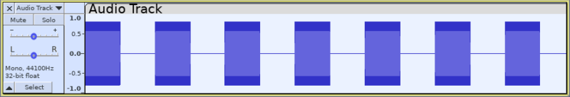
Here is the original recorded signal:

The signal waveform rises from just above zero (digital “off” state) to around 0.5 (digital “on” state). Neither the “on” state nor the “off” state are very steady, and the transition from one state to the other is not as steep as a digital switch so we shall use some Nyquist code to improve this.
There are several ways that this could be accomplished and this is just one method.
Assuming that we want the signal to rise from the centre zero line to some positive value. First we apply a bias to roughly centre the signal around zero. This is not critical as long as the signal crosses zero.
|
1 2 |
(setq adjusted-bias (sum *track* -0.2)) |
(An alternative way to centre the waveform would be to use a high-pass filter with a low filter frequency).
Amplify the result massively so that the signal in the range +/- 1 is crossing zero (almost) vertically.
|
1 2 |
(setq amplified (mult adjusted-bias 1000)) |
Clip the signal to within the required range – here we are clipping at +/- 0.4
|
1 2 |
(setf clip-amplitude-range (clip amplified 0.4)) |
Add a DC bias to make the signal rise from zero to the positive value
|
1 2 |
(setq make-positive-pulse (sum clip-amplitude-range 0.4)) |
The code above may be put together in one command:
|
1 2 |
(sum (clip (mult (sum *track* -0.2) 1000) 0.4) 0.4) |
And here is the processed track

We could also put this together with the code to modulate the signal with a high frequency (19kHz) carrier, but note that the track would need to use a high sample rate to support the 19 kHz wave:
|
1 2 |
(mult (sum (clip (mult (sum s -0.2) 1000) 0.4) 0.4)(osc-pulse 19000 0)) |
Very long lines are not easily readable, so we can rewrite it in easier to read bite-size lines:
|
1 2 3 4 |
(let ((mysound (mult (sum *track* -0.2) 1000))) (setf mysound (sum 0.4 (clip mysound 0.4))) (mult mysound (osc-pulse 19000 0))) |
And then the output is like this:

In practice, the device may work better with a sine wave carrier, in which case the code would be:
|
1 2 3 4 5 |
(let ((mysound (sum *track* -0.2))) (setf mysound (clip (mult mysound 1000) 0.4)) (setf mysound (sum 0.4 mysound)) (mult mysound (hzosc 19000))) |
And the final result: